Method of Joints: Method of joints is usually used when we are interested in finding the internal force in every single member of the truss. As its name implies, it relies on the application of equilibrium condition at each joint to solve for the member forces.
To start the analysis, it is best to draw a detailed free-body diagram, or an exploded view,of the truss as shown below. Since the members at each joint are held together by a single frictionless pin, then the exploded view should also include the free-body diagrams of these pins. Each member force is represented by a unique name in blue color. Notice that the external forces are shown acting on the joints and not the members. Also to simplify the analysis, all member forces in the preliminary free-body diagram are shown to be in tension. If the solution produces a negative member force, it indicates that its correct direction is opposite to that assumed.
With all reactions calculated previously, we will consider one joint at a time, and solve for the unknown member forces at that joint. The main factor to remember is the so-called feasibility condition,that is the joint being analyzed has to have at least one known force and at most two unknown forces acting on it. Otherwise, there will be more unknowns than the number of equilibrium equations available to solve for them.
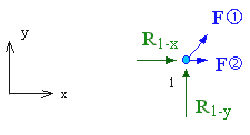
In this example, the analysis can begin from either joint 1 or 4 as both joints meet the feasibility condition. The free-body diagram of joint 1 is shown below

The forces acting on a truss joint form a coplanar, concurrent
force system. Therefore, only the equilibrium of forces in the
horizontal and vertical directions can be used to solve for the
unknowns. For joint 1 these equations are used to solve for F![]() and F
and F![]() that are the
axial forces in members 1 and 2.
that are the
axial forces in members 1 and 2.
| ΣFy = 0 | => | R1-y + [
(y6 - y1) / l |
where l![]() is the length of member 1, and
the term inside brackets is the direction cosine associated with
F
is the length of member 1, and
the term inside brackets is the direction cosine associated with
F![]() .
.
| ΣFx = 0 | => | R1-x +
F |
With the unknown forces at the starting joint found, the focus shifts to another joint that meets the feasibility condition. In this example, that would be joint 2. We did not pick joint 6 as it violates the feasibility condition with more than two unknown forces. This process is repeated for as many joints as necessary until all member forces are determined.
Once all the member forces are found, then the directions of internal forces determined to be negative can be corrected in the exploded diagram of the truss. Showing member forces in correct directions helps to identify which members are in tension and which are in compression. This difference is crucial as members in compression should be designed mainly against static instability known as buckling, and those in tension should be designed based on the allowable tensile strength of the material.
