Section A16.2 example 3
SECTION
A16.2 EXAMPLE
3
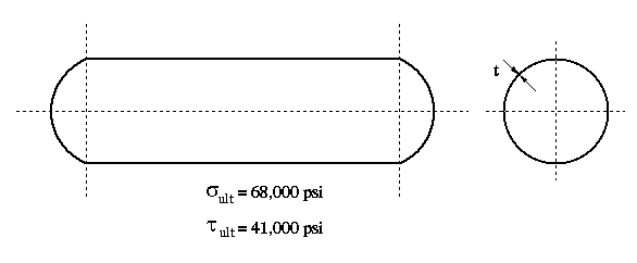
An idealized transport aircraft fuselage, shown in the figure below, is to be
fabricated from aluminum alloy with the ultimate stresses shown. Knowing that
a maximum allowable gauge pressure of 14.7 psi is desired and factors of safety
of 1.5 in tension and 2 in shear are required, determine the minumum allowable
skin thickness. The diameter is 72 inches. The end caps are spherical, and
have the same thickness as the cylindrical section.
EQUATIONS
USED


SOLUTION
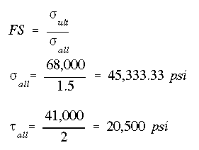
First, we determine the allowable stresses as
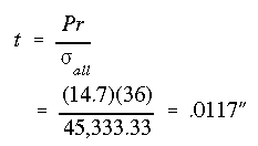
For each section of the fuselage we find the skin thickness based on each
equation. The largest value will be the minimum allowable skin thickness.
Cylindrical Portion:
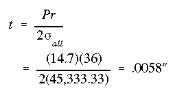
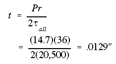
Spherical Portion:
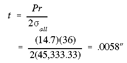
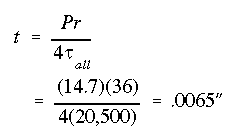
The minimum allowable skin thickness is

 To Section A16.2
 To Index Page of
Internal Pressure


 To Section A16.2
 To Index Page of
Internal Pressure