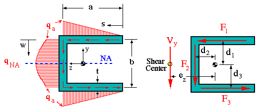
To calculate the shear flow over a section of interest we must have the value of transverse shear force V that is acting along a principal axis. This force is either given or should be obtained from the shear diagram. Then we need to have the moment of inertia about an axis that is perpendicular to the direction of the transverse shear force. For example, if V is along y, we need to have Iz, or if V is along z, we need to calculate Iy. With Vz/Iy or Vy/Iz known, we calculate the first moment of area, Q. If V is along the y direction, we need to calculate Q about the z axis. To do this a segment of the cross section is isolated from the rest, and its moment about the z axis is calculated. The way we isolate a segment is by cutting it perpendicular to its thickness. We will see how this is done in the example problems at the end of this section. An example of a shear flow diagram is shown below.

Notice that in this example, the transverse shear load is in the vertical direction. Thus, the moment of inertia about the horizontal centroidal axis is used for the calculation of shear flow. The shear flows along the top flange and the web are calculated as


The direction of shear flow has to be consistent with that of the resultant shear force, in this case Vy.
We can also calculate the shear force acting in each member. To do this, we simply integrate the shear flow along each member.

Key Observation:
If we examine the internal shear force distribution we observe the following facts. Since the resultant shear force is in vertical direction, the two flange forces (in horizontal direction) will add up to zero as they should. However, if we compare the force in the vertical web, F2 to Vy we find that they are not the same. Although this may indicate that force equilibrium is violated, the fact is otherwise. We know from previous discussion that shear stress at a given point is represented in terms of its two perpendicular components. We also said that usually one component is much larger than the other. In this case the vertical component of shear stress in top and bottom flanges is much smaller than its horizontal component but not necessarily zero. If we were to consider the vertical component of shear stress in the two flanges and calculate the corresponding shear force, we will find that they added with F2 will be equal to Vy.
The reason we don't go through the trouble of calculating these forces is because they are much smaller than F2. In fact we can see that if b > > t, then F2 is > 90% of Vy. It is important to know this fact when doing bending analysis under transverse loads.
Shear Center Calculation:
The shear center is found using moment equilibrium. We show the resultant transverse shear force acting at the shear center which is at some distance e from the point of reference, usually the centroid of the cross section. We then write the moment produced by the resultant shear force V, set it equal to the sum of moments produced by individual internal force components, F1, F2 and F3, and solve for the unknown distance, ez in this case. Paying attention to the direction of each moment, we can write

Beam Sections Not Loaded Through the Shear Center:
If the applied shear force does not pass through the shear center, it will force the beam to twist as it bends. This eccentricity produces a torque, that will cause an additional shear flow and shear stress. The analysis used for torsion of beams with open cross sections (I.4) can be used here to find the constant shear flow and corresponding shear stress at a desired point on the cross section.
In analysis of such sections, the shear force is
replaced by an equivalent force-couple at the shear center.
The final shear stress diagram will be the superposition of
1. the shear stress with the shear force passing through the shear center,and
2. the shear stress induced by the associated torque about the shear center.
An example of this kind of loading is shown below. Note that in this case, the maximum shear stress occurs at a point on the neutral axis which is on the left edge of the vertical flange.

Shear Force in Fasteners:
In many applications, beam sections consist of several pieces of material that are attached together in a number ways: bolts, rivets, nails, glue, weld, etc. In such so called built-up sections we are interested in knowing the amount of shear stress and the resulting shear force at the cross section of fasteners or over the glued surface.
The figure shown below gives an example of two rectangular members that are attached by means of mechanical fasteners. In this case, we want to know the amount of shear stress as well as shear force carried by each fastener. The fasteners are spaced evenly at a distance of s. Each fastener has a cross-sectional area denoted by Af.


Note that the surface of contact or joint is treated as a frictionless surface. Therefore, the shear flow is carried entirely by the fasteners.
If at a given section, there are more than one fastener, the shear flow will maintain the same value, but the shear force and shear stress will change depending on the number and size of fasteners used. For example, if at a given section there are two identical fasteners as shown below, then the force in each is found as shown below.


 To Section
III.5
 To Index Page of
Transverse Shear Loading of Open Sections