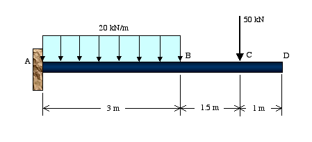
Example 2: For each beam shown, draw the free-body diagram and discuss the support reactions present.
Figure a
(Move the mouse over the figure to see the free-body diagram.)
In Figure a, the beam is supported by a pin or hinge at point A and by a roller at D. Therefore, the reaction force at A can be shown in terms of its two rectangular components RAx and RAy. The sense of each reaction component is assumed at this point pending the use of equilibrium equations. The reaction at D has to be in the vertical direction or perpendicular to the support surface. Because a roller can only be compressed, the direction of RDy would be upward in this case.Also notice that the distributed force is replaced by its corresponding resultant acting through its centroid. Having drawn the complete free-body diagram, we can identify the unknown loads and solve for their magnitudes using the equations of equilibrium.
Figure b
(Move the mouse over the figure to see the free-body diagram.)
In Figure b, the beam is supported by a pin support at A and by the brace strut BE. The beam is connected to the strut by a pin at B. We draw the free-body diagram of the beam by separating it from its supports at A and B. The reaction force at A is represented in terms of its x and y components. A close examination of the frame indicates that member BE is a two-force member. Therefore, the force at point B must be along the straight line connecting points B and E. In this case, the strut is assumed to be in compression, so the force is shown to be pushing on point B.Similar to the previous case, the distributed force is replaced by its resultant acting through its centroid.
Figure c
(Move the mouse over the figure to see the free-body diagram.)
In Figure c, the beam is fixed at point A and free at D. This is known as a cantilever beam. The fixed end prevents the beam from having any translation or rotation. Therefore, there are two reaction forces and one reaction moment at A.

