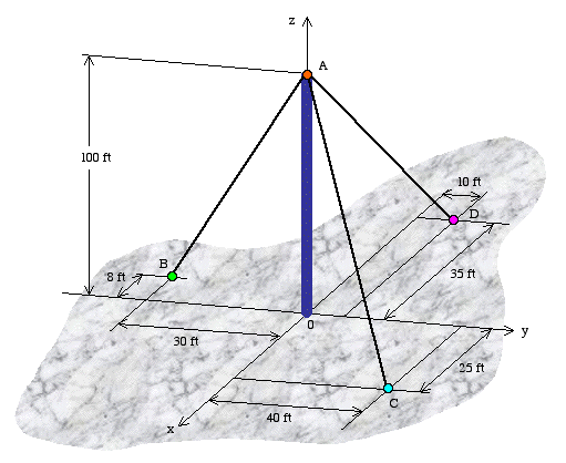
Example 4: An antenna tower is held in the vertical position with the help of three cables. The tensile force in cable AB is 2,000 lb, in AC is 2,500 lb, and in AD is 2,200 lb. Based on the geometry shown below, determine
- the magnitude and direction of the resultant force acting on the antenna at A,
- the angle between cables AB and AC.

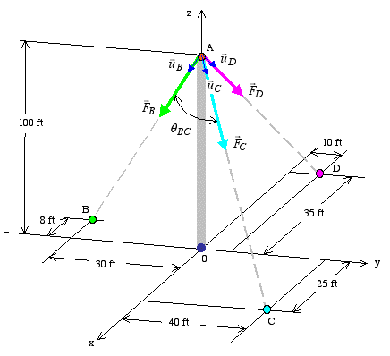
Solution: We begin the analysis by drawing the known force vectors acting through point A for clarity.

Part a: We are given the magnitude of tension in each cable, but not its direction. So we begin by first calculating the unit vector associated with each force. To do this, we make use of the position vector measured from point A to each of the three base support points in xy plane. Knowing the coordinates A(0,0,100), B(-8,-30,0), C(25,40,0), and D(-35,10,0), we get


Next, we divide each position vector by its magnitude to find the corresponding unit vector.


With each unit vector known, we can express the tension in each cable as


Now, a simple vector addition will give us the resultant force vector

The magnitude of the resultant force is found as
![]()
The direction of the resultant force can be defined in terms of the unit vector in the same direction.

The unit vector indicates that the resultant force is very close to being completely in the -z direction. To check the validity of this result, we can go back and take a look at the individual forces found previously. When we look at the three forces, we find that not only all three have a negative z component, but that the z component in each case is much larger that the other two.
Part b: To find the angle between cables AB and AC, we use the dot product between any vector along AB with any vector along AC. Recall that the dot product between two vectors can be expressed as
![]()
where represents the angle between vectors and . Using the position vectors along AB and AC we find the desired angle as

![]()
Modification of Antenna Tower Design: Having done the force analysis, we can determine whether the tower will be held in the vertical position as was originally intended. And if not, what modifications can be made to it to keep it vertical.
A tower of this type is usually supported at its base by a ball and socket so that there is no moment at the base, and the cables can be adjusted to position the tower in the desired orientation.
Therefore, to keep the tower vertical, the direction of the resultant force has to be completely vertical (in the z direction). To achieve this objective, we must adjust the support cables. Since a force vector consists of both magnitude and direction, we can either adjust the magnitude of forces in the cables, or move the base end of one or more cables to change the direction of the resultant force.
Alternative 1:Let's consider the case of adjusting the tension in the cables with the help of turnbuckles. Also let us assume that a resultant force of 6,300 lb is acceptable in this case. Therefore, we can proceed as follows. The intent is to have the resultant force vector be defined as
![]()
Since we are keeping the direction of each cable force the same, we can write the cable force vectors as


Knowing that
![]()
we can write
![]()
![]()
![]()
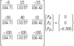
This system of linear equations can be expressed in matrix form as

The solution of this matrix equation gives

As can be seen, a considerable tension increase in cable AB is needed to meet this objective.
If we find this change unacceptable, as the tension in cable AB may be greater than what it can handle, then we must consider moving the base point of one or more cables as discussed next.
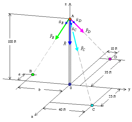
Alternative 2: In this case, we will keep the cable forces as originally stated, and consider changing the location of point B to a point in xy plane such that the direction of the resultant force will be in the z axis.

We can start from the scalar equations
![]()
![]()
![]()
We know the magnitude of force in each cable. We also know the unit vectors in direction of AC, AD and R. Making the proper substitutions gives
![]()
![]()
![]()
In addition to the above equations we know that
![]()
From the solution of these four equations we get

Having found the components of the force vector in cable AB, we can express the unit vector along that cable as

Recognizing the equality of corresponding terms in the right sides of the two equations and the fact that point B is in xy plane, we can write


Recognizing that
![]()
we find
![]()
Comparing the new location of point B to that specified in the original problem, we see that it needs to be moved 1.56 ft more in the x direction but 37.12 ft more in the y direction.
It is important that we always be aware of such design issues as discussed in this example, and make rational decisions in modifying the design based on proper engineering analysis.