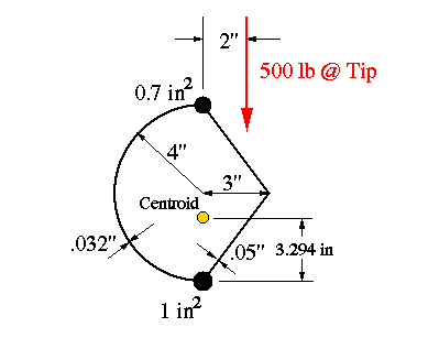


and equations of equilibrium
(a)
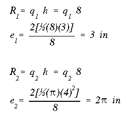
In this problem there are 4 unknown force quantities, 2 shear flows and 2 axial loads. Therefore, we can use the equations of equilibrium. But first, the force in each web must be determined. Recall from section A14.9 that the magnitude and location of the resultant force of the shear flow in a web are found using

For this problem, it is nessecary to leave 'R' in terms of the shear flow 'q'.
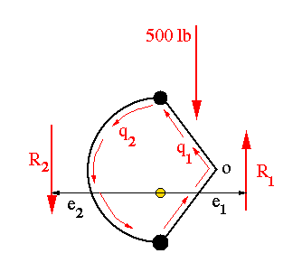
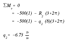
Now sum the moments about point 'o'. Note that since R1 passes through this point, q1 will not appear in the moment equilibrium equation. Hence, we can directly solve for q2.
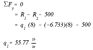
Now sum the vertical forces to solve for q1.
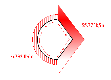
The shear flow diagram is shown in the figure below.
The calculation of axial forces in the flanges or stringers is fairly straight forward. We first draw the free-body diagram of the box beam by separating the webs and flanges as shown in the figure below.
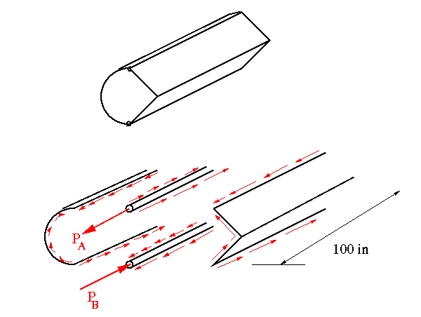
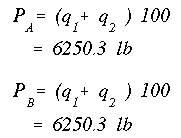
Knowing the direction of shear flow in each web, the direction of shear flow in the flanges can be determined. The axial force in each flange will be the sum of shear flows acting on it multiplied times the length. Notice that there is no axial force at the tip end of each flange.
Now we have determined all the unknowns asked for in the problem statement. Take a moment to go back and review the solution procedure to make sure you understood all the steps involved.
You should have noticed that we only used three of the six equilibrium equations. It would have been possible to calculate the forces PA and PB without having to draw the free-body diagrams. We could have just summed forces along the length of the box beam to obtain one equation in terms of PA and PB. This equation would have indicated that PA = PB immediately. Then, we would have used a moment equation about a horizontal line perpendicular to the length of box beam and passing through either point A or B. This way we could find the magnitude of the unknown force. Try this approach to make sure you will get the same answer as shown in the solution.
(c)
To determine the horizontal position of the shear center, we assume that the vertical force of 500 lb is acting at a distance of ex to the right of stiffeners. The following procedure is used to determine the value of ex.
Recall that by definition, if a transverse force passes through the shear center of a section, it will cause the beam to bend without twisting. Therefore, if the 500 lb force is passing through the shear center, as considered in this section, then the angle of twist, theta, should be zero.
We begin by writing the summation of moments about point A
Next, we sum forces in the vertical direction.
The last equation is that for the angle of twist
Solving equations (1) through (3) simultaneously gives
Now, we have found the horizontal position of the shear center. The negative sign indicates that the shear center is to the left of stiffener A and not to the right as originally assumed. We have also determined the values of the shear flows in the two webs when the transverse shear resultant passes through the shear center.
 To Section IV.2
 To Index Page of
Transverse Shear Loading of Closed Sections