


(a)
At first glance, we can tell that this is a statically indeterminate problem. There are 7 unknown forces and shear flows, but we only have 6 static equilibrium equations to work with.
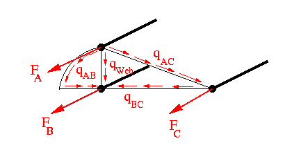
However, if we include the angle of twist equation, there will be sufficient equations to solve for all the unkowns in the problem.
Start by summing the vertical and horizontal forces and the moments about stringer A using the view shown in the figure below.
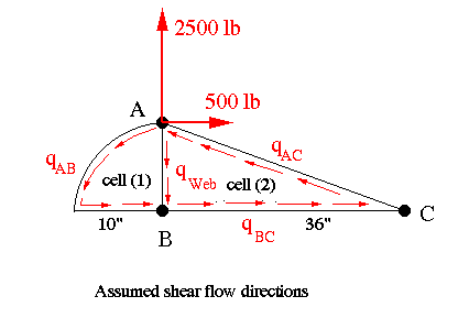
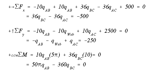
The equilibrium equations are
Now write the angle of twist equation for each cell. Since the angle of twist in the two cells must be equal, we can set the right hand sides of these equations equal to each other and obtain an additional equation in terms of the unknown shear flows.
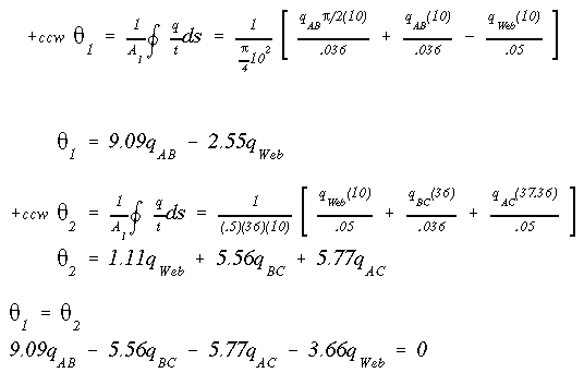
We now have 4 equations and 4 unknowns. Solving them gives the shear flows as
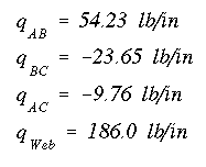
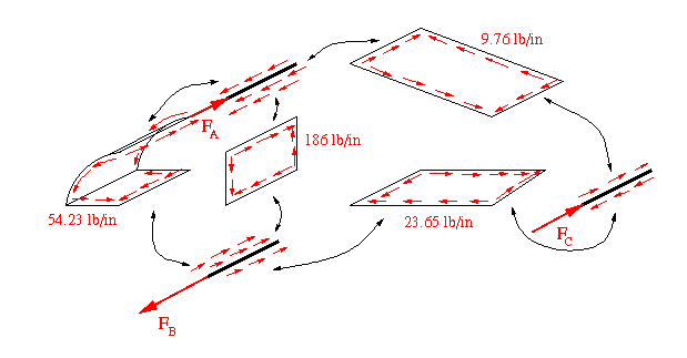
The axial forces are found by breaking up the wing section and drawing the shear flows on the panels and stringers.
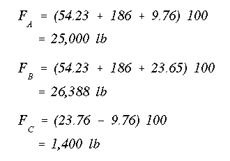
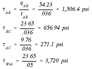
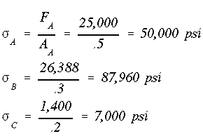
The shear stresses in the webs are found simply by dividing the shear flow in the web by the corresponding web thickness. The normal stress in each stringer is found by dividing the axial force by the area of that stringer.
To find the x component of the shear center, apply the 2500 lb load to the cross section and remove the 500 lb load. Again use the summation of forces in the vertical and horizontal directions and summation of moments, along with the angle of twist for each cell (the same way as found earlier).
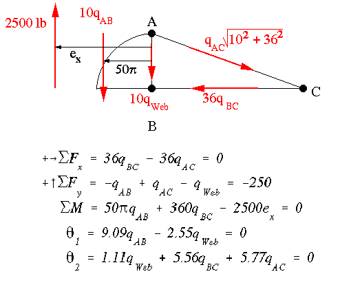
We have 5 equations and 5 unknowns. Solving for ex yields

To find the vertical component of the shear center, remove the 2500 lb load and replace the 500 lb load. Then use the same method to find ey.


With the cross section having no centroidal axis of symmetry, we cannot directly solve for the vertical tip deflection based on the formula

This equation gives the correct answer only if x and y are principal axes. In this problem x and y are not the principal axes as neither one is an axis of symmetry. Hence, what we need to do is to first locate the principal axes, then calculate the corresponding moments of inertia. Then by transforming the forces in the directions of principal axes, we solve for the tip deflection.
The cross-sectional centroid is located at (7.2",5") from flange B. The corresponding moments of inertia are calculated to be Ix = 25 in^4, Iy = 207.36 in^4, and Ixy = -36 in^4. Using the equations for the principal plane and corresponding moments of inertia, we obtain Ixp = 214.21 in^4 and Iyp = 18.15 in^4 with yp axis being at 10.77 degrees counter-clockwise from the x axis. Transforming the applied forces in xp and yp directions gives Pxp =-2,362.49 lb, and Pyp = 958.47 lb. Now using the deflection equations for the tip-loaded cantilever beam, we obtain 4.34" and 0.15" in -xp and yp directions, respectively. These values correspond to E = 10 Msi. These results translate into a tip deflection of (x,y) = (-0.67,4.3"). Therefore, the tip would deflect upward and to the left (as viewed from the root) as a result of the loads and the cross-sectional geometry.
If we calculate the tip deflection by disregarding the facts stated above, we would end up with a tip deflection of (x,y) = (.08",3.33"). This would result in error of 22.6% in vertical deflection.
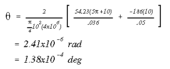
The twist at the tip is found by using the angle of twist equation for either of the two cells; the answer will come out the same, regardless of which cell is used.
NOTE:
In this example problem we used the equations of equilibrium along with the angle of twist equation to solve for the unknown shear flow and axial forces. Here is the procedure for solving for the shear flows using the direct method:
As before we need to remove some webs to create an open section. The choice of which webs to remove is arbitrary so long as once these webs are removed the section will be fully open. For example if we remove the curved and flat webs connecting stringers A and B, we will have an open section consisting of only two webs and three stringers. Now, we use the general shear flow equation to solve for the preliminary shear flow q' along the remaining webs. Note that we have to do this once with only Vy as the resultant shear force, and another time with Vx as the only resultant force.
Once the q' values are found, we will replace the webs that were removed earlier. Because of having two cells, we show two constant shear flows qo1 and qo2 in cells one and two, respectively. We write the angle of twist equation for each cell with q along each web being the algebraic sum of q' and qo. By setting the angle of twist in both cells equal, we will have one equation in two unknows qo1 and qo2. Next, we write the equation for the summation of moments about an arbitrary point. This will give another equation in terms of qo1 and qo2. Solving them simultaneously gives the two constant values. The actual values of the shear flows are found by algebraic addition of qo's and q' values in all webs. We have to pay attention to the sign of each component in finding the actual shear flows.
Having found the shear flows in the webs, we can then draw the free-body diagram of the beam to solve for the axial forces in the stringers as was done in the solution above. The described procedure is what we would use in the case of multiple-cell multiple-flange box beams to be discussed next.
 To Section IV.4
 To Index Page of
Transverse Shear Loading of Closed Sections