Use the Java screen below to change problem data and see the results.

Use the Java screen below to change problem data and see the results.


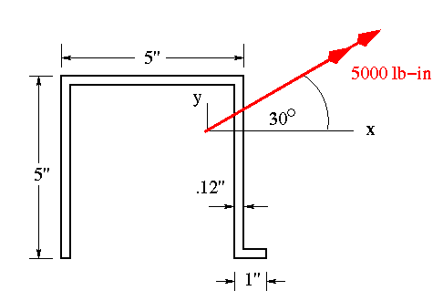
This problem requires more analysis as both the loading and cross-sectional shape are unsymmetric. The procedure is similar to the previous example. First need to find the centroid, moments of inertia about the x and y axes, and the product of inertia.
The centroid is at

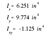
and the moments of inertia and product of inertia are

The components of the applied bending moment are determined as

The x component is negative because it causes tension in the first quadrant.
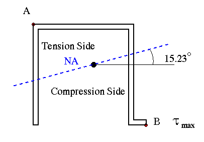
(a) Since this is a homogeneous section, and it is assumed to be within its elastic limits, the neutral axis will pass through the centroid. Its angle with respect to the x axis is

(b) The maximum bending stress occurs at the farthest point from the NA, either at point A or B.

Therefore, point B is the location of maximum bending stress.

 To Next Example